The general table in the downlink carrier node enables you to turn the downlink carrier on and off, select a predefined channel configuration, and view the length of the generated waveform.
The Baseband parameters for the downlink carrier are described in Baseband (Basic LTE-A FDD Downlink).
Double-click or use the drop-down menu to turn the carrier Off or On.
This State parameter and the State parameter in the Carrier Aggregation node are coupled.
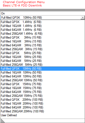
Select a channel configuration with the desired modulation
type, bandwidth, and the number of resource blocks (RB)
from the ![]() drop-down menu.
drop-down menu.
The setting is not selectable until certain parameters are changed (e.g. in the Component Carrier node: State, Auto Symbol Rolloff Length Configuration, Baseband Filter; and in the Downlink node: Total Number of Antennas, System Bandwidth, ...) then is automatically set by the software.
Choice: 1 slot (0.5 ms) | 2 slots (1.0 ms) | … | 18 slots (9.0 ms) | 19 slots (9.5 ms) | 1 frame (10 ms)
Default: 1 frame (10 ms)
Displays the waveform generation length and this parameter is read only. Total Sample Points is based on the selected Waveform Generation Length and Oversampling Ratio as shown below:
Total Sample Points = Base Sampling Rate (MHz) × Oversampling Ratio × 1000 × Waveform Generation Length (ms).
Figure 1 shows the generic frame structure.
Figure 1. Generic radio frame structure
Range: 0 to 19 slots
Default: 0 slot
Sets the waveform generation offset.
When the waveform generation length or offset is set, Waveform Generation Length + Waveform Generation Offset <= 1 frame (10 ms) is automatically satisfied by the software.